Legs and Curves
- Dominik
- Mar 15, 2020
- 9 min read
If by now you have managed to bring one of your dear tube treasures back to life or you have just acquired a perfectly working vintage specimen, you might ask yourself how to determine the status of its tubes and which types might be suitable for replacement. While in the good old times there was a dedicated testing device in almost every workshop that could quickly provide information about the condition of a used tube, this has become a little bit trickier these days.
When checking your inventory, you might find some tubes in their original packaging which look very similar to those in your amplifier, but with a slightly different letter/number combination... and now you're wondering if an EF804 can be replaced by an EF800 or an EF806. After all, they pretty much look the same? Or you may find some dusty old tubes with their labeling no longer clearly readable. Take the E88CC and E83CC for example: Similar to each other, but not compatible at all. A little scratch on the printing: Hello detective work! Often the labeling can be destroyed by accident, just by touching it with the fingers. But what happens if you replace tubes that look almost identical to each other, both in terms of appearance and labeling?

In order to prevent the discovery journey into vintage sound worlds from being ended early by making mistakes, let's have a closer look at the tube itself in this episode. I would like to show you how individual types differ from each other, how they are connected, under which conditions they work, and how an unknown tube including its condition can be identified by measuring with simple means. Anyone who has looked at tube tables from the Internet or in printed form will know that several types are very similar – whether in terms of the designation, socket connection, appearance or technical data. But which tube can actually be replaced by another one?
Tube Identification
AC701, EC 92, ECC83, EF804, EAA91, EL84 and the plethora of other cryptic names can really be confusing. However, especially tubes following the European type code which has been in use since 1934 can be determined quite well. The first letter refers to the heater, the second, third and sometimes fourth indicate the tube type. Finally, the following number indicates the socket – Mini or Noval, for example. If the first letter is followed by a number and then the other letters, or if the letters are followed by three numbers, then we are dealing with a low tolerance long-life tube. These were specially manufactured for professional use with a very low failure rate.
A Little Table
First letter:
A = 4 volts heating
E = 6.3 volts heating
Second and further letters:
A = Diode
C = Triode
F= Pentode
L= Power pentode
90 or 900: Mini socket 7-pole
80 or 800: Noval socket 9-pole
70 or 700: Wires for direct soldering
Example: EC92. This is a triode "C" with 7-pin "92" socket. It requires 6.3 Volt "E" heating voltage. Or the E88CC, a double triode "CC" with 9-pin "88" socket with "E" 6.3 Volt heating.
When it comes to American tubes, there is not necessarily the same logic explaining the type. Here, the first number(s) refer(s) to the heater voltage and the last usually refers to the number of connected base pins. Over the Ocean, the ECC81 is called 12AT7. The heating voltage (12.6V) is labeled more accurately than in Europe and 7 pins are occupied if the center tap is counted. Confused now? Don't worry, more on this later. The EC92 finds its equivalent in the 6AB4: 6.3 volts heater, and yet only 3 pins are used. From the approx. 80 different audio tubes with about 30 different socket wirings I will just present some of the most important ones which are often found in classic studio amplifiers.
Looking at the Socket
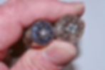
The two most common tube sockets are the Mini (left) and the Noval socket (right). If the tubes are held as shown in the photo, the connection pins are counted clockwise, starting with "1" at the right of the gap (which also mechanically prevents incorrect insertion of a tube). The same order is also found in the socket diagrams in common tube tables.
In 99 percent of all tubes with these sockets, pins 3 and 4 on the Mini socket and pins 4 and 5 on the Noval socket are the filament connections. Here you have the first opportunity to test a tube: An ohmmeter attached to these pins should read between 3 and 12 ohms. The heating filament is working fine in this case. Further tube tests without a specialized measuring device are only possible within the circuit/the device. But even then, the procedure is not so difficult. Let’s take the triode EC92 as an example, a tube which is used in the Microtech Gefell microphone amplifier CMV 563.

I have chosen the EC92 socket and a circuit excerpt using this tube to show that it is not difficult to determine possible malfunctions of a tube by means of some voltage measurements. If the values at the terminals of a tube differ significantly from their reference values, then the device, the components surrounding the tube or the tube itself are faulty. The reason that there are certain standard values for the voltages at the individual tube electrodes is that for audio purposes, almost all of the tubes considered here only work correctly within a certain parameter range. This is defined by the individual characteristic curve of each tube, which is given by the dependence of grid voltage and anode current. This characteristic curve provides information about the actual amplification.

Although this basic circuit shown in the example requires only a few components, it absolutely is a full-fledged amplifier. The two capacitors C1 and C2 are important: The task of C1 is to separate the negative grid bias voltage of the tube from the low frequency AC voltage to be amplified. An input transformer can be connected here, for example. C2, on the other hand, is particularly important because it separates the anode voltage of 200 volts from the amplified low frequency AC voltage, which at this point may just be 1.5 volts. This type of amplifier has a gain of approx. 20 dB.
A Bit of Theory
The voltage and current values given in the circuit are reflected in the characteristic curve: The respective anode voltage is indicated next to the individual graphs.

The X-axis shows the negative grid voltage of the control grid and the Y-axis shows the anode current. When searching for the negative grid voltage, you only see the value of +1.5 volts at the cathode. This is a completely typical value in tube technology: The current flowing through the tube creates a voltage drop at resistor Rk, the cathode becomes slightly positive, the grid remains at ground via Rg and thus is negative towards the cathode. If we look at the curve area marked green, the tube works very linear with minimum distortion, while operation in the red area causes 2nd degree harmonic distortion (k2).
Back to Practice
Triodes are frequently used in studio amplifier technology, and most of them are designed as double triodes (ECC system). Starting in microphones as impedance converter, followed by microphone amplifiers, up to the famous compressors by Fairchild or Altec... tubes with Noval base and the visible double system can be found all over the place.


Especially when it comes to double triodes there are some serious differences to consider. ECC81, 82 and 83 for example: Although the "E" indicates 6.3 volts heating, these tubes have a heating voltage requirement of 12.6 volts when supplied via pins 4 and 5. But if you short-circuit these two pins, the tube can be heated with 6.3 volts between these and pin 9. Such tubes have a heating with a center tap! The same applies to the 6072 inside the AKG C12 microphone impedance converter: It is also a double triode that can be heated with 6.3 as well as with 12.6 volts. The triode systems of these tubes also have very different data and characteristics. In the E88CC the heating voltage is 6.3 volts between pin 4 and 5, while pin 9 is a shield.
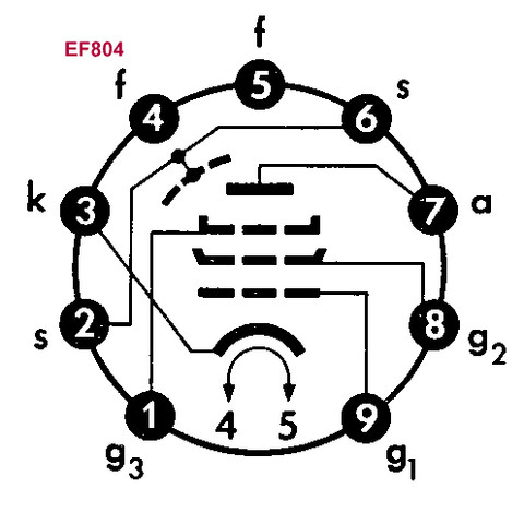
And now on to the pentodes, i.e. tubes carrying the letter "F" for identification. Here, the EF804 or EF804S should get special attention, because according to Telefunken research reports, this is the quietest tube ever built.
This type, designed for the most demanding audio amplifiers, has no counterpart to replace it. The socket circuitry is unique as well. It can only be substituted by the EF804S – a tube with a special cathode. Special cathodes are designed for applications where a tube can be operated for a long time in a heated state without anode voltage and without "poisoning" the cathode as a result. In this context, poisoning means that the cathode layer is detached from its carrier, which results in an increased noise floor.
The situation is different with the EF80. This can be easily exchanged for an EF85, EF805S, EF183, EF184, 6BX6 or 6BY7, with only minor differences in function. The same applies to the EF86, a very common LF tube. Exchanging it for an EF806S even has advantages (see above). The American type "6267" is also fully compatible.


Caution, please! Replacing an EF804 with an EF806 or vice versa is fatal – for the device as well as for the tubes.
A Simple Pentode Amplifier
The following circuit excerpt briefly explains which voltages are usually measured on a pentode. You can see the anode voltage and the voltage at the cathode, which, due to the flowing anode current, becomes the negative grid bias voltage. What’s new here is the middle grid (G2) which is fixed at 220 volts and grid 3, which – well grounded – sends the rebounding secondary electrons back shortly before they reach the anode (which helps to linearize the characteristic curve).

Here, too, significant deviations in the measured values indicate a malfunction. If, for example, the voltage at grid 2 is missing because the capacitor has blown or the resistor has an interruption, the amplifier will remain silent. In this case you can help yourself quite easily: By connecting grid 2 to the anode, the tube will continue to operate in triode mode. The sound will change slightly, and that’s it.
Testing Tubes
The best tube tester is always the device in which a tube is used in. When it comes to IRT (Institut für Rundfunktechnik) based amplifier designs, the correct voltages for the individual electrodes are usually mentioned in the schematics. A worn-out tube can be recognized by the fact that its cathode loses in emissivity, which causes the anode current to drop, so that the voltage at the individual electrodes rises above the specified value. From experience I can say: Impairments caused by worn out tubes sometimes only start to become audible when they have less than 50% of their nominal emissivity. Then, however, these tubes are conspicuous by a strong decrease in the reproduction of the low frequencies: Bass appears blurred.
Some Detective Work
For those who have acquired further interest and would like to take a closer look at their vintage audio treasures, here are a few tips for identifying tubes which have lost their printing. An experienced look inside, checking how the pins are connected to the individual electrodes such as grid, cathode or anode, can be all it takes. For the following photo I had to slaughter an EF86, so the inner connections became way more obvious for demonstration.
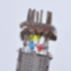
With some practice you can find the connections of the cathode (marked red), the heating connections (yellow) and the anode (blue), and then use this knowledge to identify the tube by comparing it using a tube table, like the EF806 socket diagram above. The cathode (3) and anode (5) are located next to heater terminals 4 and 5. If this has worked, the probability of serious problems caused by a replacement is low. Different currents can still lead to an unsatisfactory result, however. For example, a higher anode current affects the grid bias voltage and the tube may operate in the non-linear part of the characteristic curve, resulting in distortion. Caution is due, of course, because too high a current is likely to heat the resistors up due to overload.
I hope I was able to further interest you in this new old technology. For me, the fascinating thing about tube circuitry is its incredible simplicity. It's all about achieving great precision with a few high-quality components!
My Sources
All connection diagrams, characteristic curves and circuit diagrams are taken from original Telefunken tube manuals. Reprinting is permitted, provided the source is mentioned, which I have just done with pleasure.
Let me repeat this very, very important piece of advice: Tube units work with life-threatening voltages! In addition, I would like to point out that even a unit disconnected from mains may still contain dangerous charges in its capacitors!
Preview
In the next episode, we will leave the classic tube machines for a while. As is well known, the technological successor of the tube was the transistor, invented in 1949, which evolved from the germanium type to the integrated circuit with hundreds of components in a very small footprint. We will have a good look at classic transistor devices, what to consider when restoring a FET compressor, which problems to expect when using tantalum capacitors and so on.
This article is presented with kind permission of its original publisher, the amazing Studio Magazin, enriching Pro Audio since 1978! The author, Uli Apel, is an incredibly versatile and experienced engineer as well as one of the most qualified experts in vintage broadcasting and audio technology around these days.