Oscilloscope and Tone Generator
- Dominik

- Oct 21, 2021
- 9 min read
If our recent blog article has inspired you to look into the mechanics of your vintage tape machine, you might appreciate this one as well: It’s all about the electronic adjustment of our precious recording device. Most of the time, this does not even require very special equipment, which in the past could only be operated by absolute specialists (in white coats) to the great amazement of the audience.

Let’s have a look at how the heads can be adjusted and the levels can be set with quite simple measuring devices. In this article, the tape machine will be calibrated to a preferred, existing or still available tape type. Only for the adjustment of the playback section, a measuring or reference tape will be needed.
Setting up the Workplace
We will use the following tools to adjust our analog tape machine:
Slotted/crosshead screwdriver set (1.5 - 4 mm) for adjusting the level, frequency response and pre-magnetization trimmers
Set of small hex keys (1.5 - 5 mm) for calibrating the heads
Degaussing coil
Oscilloscope with two channels and corresponding probes/connectors
or correlation meter
or stereoscope
Low frequency generator as level generator (20 Hz - 20 kHz at levels between -30 and +10 dBu)
Level meter
Preparations
Before any work on the unit, the heads and all tape guides that come into contact with the tape as well as the tools used for adjustment must be demagnetized! This is done with a degaussing coil, as available in well-assorted electronics stores. But you can also make a choke yourself if you know what you’re doing. I have ‘misused’ the coil of a magnetic valve. The advantage of this is that straight tools can be demagnetized well by pulling them through the opening while the coil is activated. The process of demagnetizing the heads and tape guides happens as you can see in the picture.

It is important that the device to be demagnetized is switched off and that the coil is switched on and off at a distance of at least one meter from the workplace. This prevents objects in the vicinity from being magnetized again by the switch-off impulse. For the M15A, it is even recommended to remove the head block completely from the machine for demagnetization.
Calibration
The procedure for the electrical calibration is executed according to a schedule which must be strictly adhered to, because a deviation in the sequence will inevitably result in wrong adjustments. Although nothing can be completely destroyed by these misadjustments, it would be impossible to get a device to function like it should this way. All settings build upon each other. For demonstration, I would like to present the Telefunken M15A stereo version again, as it is well suited for a clear presentation, as previously described in the service of its mechanics.

Other fabricates can be handled in the same way, but the individual adjustment points are of course located in other places, or sometimes they are even set electronically (on Studer, for example) via +/- jog keys. Now that all parts and tools that can come into contact with the tape or the heads are demagnetized, the machine can be switched on. The outputs of the machine are connected to a studio level meter and a correlator or stereoscope. If the latter is not available, two input channels of the oscilloscope are connected to the outputs of the machine.
For a calibration of the entire device, the correct adjustment of the playback section is the first important step. This setup determines at which level and operating point the tape will be magnetized.
Since audio tape only carries a changing magnetic flux, but no levels like one is used to from studio technology, a small list is needed from which a relationship between these quantities can be seen. The following table shows the flux densities used in Germany and the corresponding (radio house) levels.
Field Strength Level in dBu Reference to Studio Standards
1028 nWb +12 dBu Maximum level with 3% THD at 1000 Hz
(e.g. EMTEC Studio-Master 900)
514 nWb +6 dBu Standard level for full modulation and 0dB display
320 nWb +2 dBu Older stereo level for 2 mm track width on ¼" tape
250 nWb +6 dBu Standard level for many cassette recorders
Most of the older reference tapes still in use today carry, in addition to the reference tone and gap adjustment sections, further various single frequency bands or recordings with sliding sine, with timings which are adapted to older frequency response recorders. For example, Brüel & Kjaer or Neutrik recorders can be synchronized this way. Reference tapes are produced for only ONE tape speed at a time.
Blue leader tape marks the reference tape for 19cm/sec and red is the color for 38cm/sec tape speed. These colors are also found on the corresponding trimmers for device synchronization.
Most reference tapes – even those with a width of up to 2" – are recorded in full track. Exceptions are some 1/4" stereo reference tapes from BASF. And by the way: The tape type (or the type designation) and the manufacturer of the reference tape do not matter at all, only the recorded flux density is decisive.

The level section on studio reference tapes is recorded with a frequency of 1000 Hz at a magnetic flux of usually 514 nWb. nWb means "nanoweber" and comes from the unit named after Wilhelm Eduard Weber, in whose honor it was so named (up to the 50s of the last century the alternative unit Milli-Maxwell was also in use). For us audio people it is comforting that the flux densities behave like the voltage levels: A doubling of the nanoweber value means a level increase of 6 dB.
Adjusting the Playback Section

Putting on the reference tape is intuitively done with a certain care, because it is the only measuring standard which all further procedures directly depend on. If you want to be very sure that no accidental erasure of the tape can happen, you can set the small switch on the erase generator board (M15A) to SAFE.
Now the machine can no longer activate its Record function. During the playback of the level part from the measuring tape one already has the first possibility to roughly check the level and the phase between the channels. If you are not sure whether the playback head is vertical, you can turn the wobble screw of the playback head back and forth. The amplitude of the signal has to be observed while doing this:
We need to adjust the maximum. The correlation degree meter should remain at +1 and the oscilloscope switched to X-Y operation should show a Lissajuos figure in the form of a dash (left image; right image shows phase problem).


This setting is quite rough at low frequencies. When the maximum is found, the level control in the playback section of the machine can be used to set the – provisionally – correct output level. With 514 nWb flux density on the tape and the help of an output level meter, exactly 0 dBr should be set here. This corresponds to a level of +6 dBu.
The next section on our reference tape is responsible for the fine adjustment of the playback head: The part for the gap adjustment. Here a frequency of 10 kHz is recorded, usually with the level reduced by 10 dB. Now, wobbling the head has a considerably greater effect, which is great for fine-tuning.
Attention: Depending on the device setup and the wobble range, there is danger here that you shift the phase beyond 180°. Then, 0° or correlation +1 is displayed again, but you have exactly this phase shift between the upper (left channel) and lower track (right channel). But then, it is only valid for the frequency 10 kHz. When playing back a different frequency, this quickly becomes obvious: The level of the recording decreases.
The further procedure concerns the equalization adjustment of the reproduction section. Usually, it is sufficient to equalize the so-called corner frequencies, i.e. the frequencies near the lower and upper end of the respective response range of the machine. It should be noted that these individual frequencies are usually recorded at a level which is 20 dB below the reference level (i.e. 51.4 nWb instead of 514 nWb).

Some manufacturers of tape machines have solved this in an elegant way by providing different adjusting screws for the lows and the highs (as seen on the photo of the amplifier magazine of the M15A). Here you can spot separate trimmers for Treble I and Treble II. This way, the playback frequency response can be linearized well with the help of the corresponding frequency response sections of the reference band. A little bit of trial and error is called for, because these settings also depend on the playback speed. At the end of the entire playback adjustment, play the tape again completely under observation of the level meter and the oscilloscope or the correlation meter. If necessary, re-adjust slightly with the appropriate trimmers. Now the machine is adjusted on the playback side.

Adjusting the Recording Section
Now carefully rewind the reference tape, remove it and put back it into safe storage. Do not place it near magnetic fields (speakers…). Place the blank tape to which the machine should be calibrated to, so the calibration of the recording section of the machine can begin. Turn the SAFE switch back to READY and connect the inputs of the machine to the LF generator. It makes sense to secure the trimmers in the playback section with tape or a small drop of varnish (make-up box: nail polish). Attention: It's easy to end up with the screwdriver in the wrong slot. If you turn and nothing happens, you've lost. This is especially true with multi-track machines.

The adjustment of the recording section is very similar to that of the playback section, except for one aspect which is typical of analog tape: With the help of pre-magnetization, the operating point for recording must be set to the corresponding tape type. Here the adjustment process differs essentially – more about this later.
First, the gap setting of the record head needs to be adjusted. Set a level of approx. -14 dBu at a frequency of approx. 10 kHz on the LF generator. Switch the machine to recording and, observing the Lissajous figure or the correlation degree meter, set the recording head vertically. The playback head serves as the measuring standard, since it is already set according to the reference band.
After this, it is possible to set the recording level on the machine for the first time: Set the LF generator to the desired level, for example +6 dBu at a frequency of 1 kHz. Use the recording level trimmer at the output of the machine to set +6 dBu. With this setting, the tape on the machine will be magnetized at 514 nWb. The next step is to set the bias. This determines the operating point at which the machine can record maximum magnetic flux onto the tape with minimum distortion.
This setting is different for each tape (type and manufacturer). The machine is calibrated to tape XYZ with this setting. On some machines (Studer, Otari) two different settings can be stored, so two different tape types can be recorded onto.
Slope and curvature of the magnetic operating characteristic of the tape depend on the pre-magnetization. Each manufacturer always supplies technical data with their tapes, also showing the pre-magnetization setting. If this information is missing, there are rule of thumb values according to which the setting can be made.
The procedure is always the same: The device is switched to record, a tone of 10 kHz is fed at a level of approx. -15 dBu. Now a maximum is sought on the level meter by turning the corresponding pre-magnetization trimmer. Then this trimmer is turned further to the right and, while observing the level meter, the pre-magnetization is increased until the level has dropped by 2 dB (for 38 cm/sec) or 3 dB (for 19 cm/sec) from to the maximum.
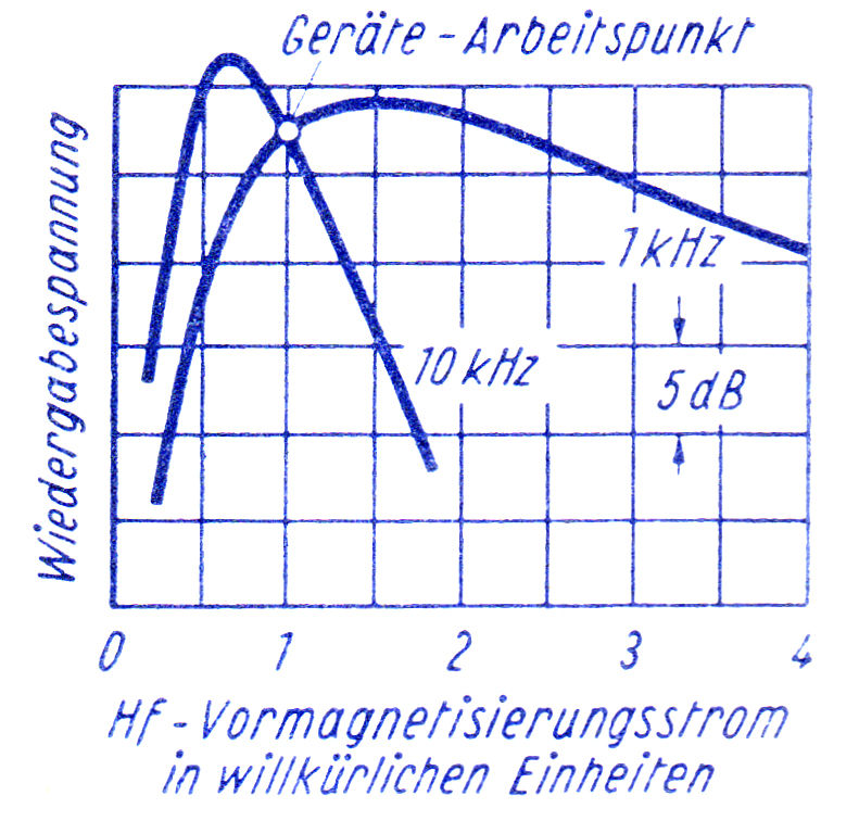
This must be set for each channel. Please do not try to set the same level for both channels here: The position of the trimmers and thus the level for the pre-magnetization can be very different. As you can see from the illustration, this setting also influences the level at 1 kHz. Therefore, feed in 1 kHz again, set +6 dBu and adjust +6 dBu at the output with the level control on the record card.
To adjust the recording frequency response, set the LF generator to 10 kHz at a level of -14 dBu and use the corresponding trimmer (treble) to set the output level to -14 dBu or -20 dBr as well. It is important to always linearize the frequency response with a level 20 dB below full-scale level.

The reason for this is the arched characteristic curve of the recording amplifier: With high frequencies as continuous tone, it would be overdriven otherwise. A further linearization of the frequency response is now possible by recording different frequencies under observation of the level meter and the adjustment of the treble trimmer.
With some practice, a fairly linear recording frequency response within certain tolerances can be achieved this way even with older machines.
Preview
In the next episode, we will have a look at various analog measuring devices for restoring classic technology and share some tips about their calibration and use.
This article is presented with kind permission of its original publisher, the amazing Studio Magazin, enriching Pro Audio since 1978! The author, Uli Apel, is an incredibly versatile and experienced engineer as well as one of the most qualified experts in vintage broadcasting and audio technology around these days.


Новини, новини і знову новини, все наразі зав'язано на новинах, без них неможливо уявити наш день, саме вони допомагають дізнаватися про всі актуальні події. З урахуванням нашого часу, я можу зі сто відсотковою впевненістю казати, що саме завдяки новинам, я відчуваю себе в ритмі життя, саме вони підтримують мене в інформаційному просторі, без них було б дуже складно орієнтуватися у тому, що взагалі відбувається. Завдяки якісному новинному порталу delo.ua, я нещодавно прочитав дуже крутий матеріал, де розповідається про те, що валютний курс досяг 42 грн/дол https://delo.ua/finance/valyutnii-kurs-dosyag-42-grndol-comu-ce-stalosya-ta-yakim-vin-bude-na-pocatku-2025-roku-439828/, дуже цікаво було читати та дізнатися думки експертів: чому це сталося та яким він буде на початку 2025 року? Дуже тішить той факт, що саме завдяки дело.юа, я почав більш детальніше слідкувати за новинами,…